How to Improve Printing Accuracy? A Look at Extrusion Width

For most 3D printer users, printing accuracy is a critical standard for evaluating a printed part. A precise term for this criterion is printing tolerance. Printing tolerance is the variance between the design of an object and the printed object’s dimensions. For example, a poorer tolerance is due to a larger variance between the CAD model and the print. Printing tolerance can be affected by many factors, and this blog entry discusses how to improve XY axis printing tolerance using a Raise3D printer with ideaMaker, regarding extrusion width factors.

How to improve XY axis printing tolerance using a Raise3D printer with ideaMaker

Tolerance existed between design and actual print

Figure: Tolerance existed between design and actual print


An FFF printed part’s exterior XY dimension is determined by the extruded thread path position and the width of the outmost thread. Assuming positioning is accurate, the deposited thread width decides the XY dimension. The Z-axis positioning decides the Z-dimensional tolerance of the printed part.
Note: Raise3D printer’s stepping precision is higher than 1 micrometer, therefore XYZ positioning variance is ignored here.

The outmost thread path position is computed by slicing software after calculating the pre-set extrusion width and the design dimensions of the STL file. For example, in ideaMaker, the common setting is an extrusion width of 0.4mm. During the slicing process, ideaMaker will calculate where to deposit the 0.4mm wide thread so that its outmost contour can fit within the dimensions determined by the design. Therefore, if the extrusion width is virtually the same as the setting in ideaMaker, the outcome will have perfect tolerance.

Flow rate will change width of outmost contour

Figure: Flow rate will change width of outmost contour


Basic Practice: Adjusting Flow Rate

Calibrating deposited thread width to reduce exterior dimension tolerance is a convenient strategy. Under ideal conditions, a change in the width of the outmost thread can directly compensate for the exterior dimension tolerance. In ideaMaker, adjusting Flow Rate can change the amount of filament extrusion by a percentage against extruder moving distance, with the extrusion path unchanged. Subsequently, the width of the squeezed thread will change. Such a mechanism can manipulate the virtual width close to a preset value, delivering a better dimensional size outcome. However, the Flow Rate cannot solve the irregularity of extrusion width along the thread, giving it a certain dimensional tolerance. In a real-world case, Flow Rate can only calibrate the average width close to a preset value. If the user wants further improvement, the user can apply additional methods.

Left with lower flow rate, right with higher flow right

Figure: Left with lower flow rate, right with higher flow right


Where to change flow rate in ideaMaker

Figure: Where to change flow rate in ideaMaker


Side Effects:

If the Flow Rate adjustment is too low, under-extrusion will occur, resulting in gaps in the infill of the top and bottom surfaces. If the Flow Rate is too high, over-extrusion will occur, causing the top and bottom surfaces to wrinkle. In such cases, the user can adjust the Top\Bottom Surface Solid Fill Extrusion Width Percentage and Speed. If the former setting cannot deliver decent surface quality, the user can activate Ironing to optimize surface quality.

Left shows under extruded surface, right shows over extruded surface

Figure: Left shows under extruded surface, right shows over extruded surface


Additional Calibration: Smaller Diameter Nozzle and Reduce Extrusion Width

Due to inevitable filament quality inconsistency, such as filament diameter and thermal expansion rate, users can reduce virtual extrusion width to improve the thread width tolerance. Generally speaking, the lower the width extrusion thread is, the less variance in its irregularity. Therefore, the user can switch to a smaller nozzle and set a lower extrusion width in ideaMaker. A method like this has a cost for certain structures. For example, the top/bottom surface will need more extrusion paths to fill up, resulting in a longer printing time.

Left shows extrusion with smaller nozzle and extrusion width value, right shows what with larger setting

Figure: Left shows extrusion with smaller nozzle and extrusion width value, right shows what with larger setting

For any further questions regarding dimensional size tolerance and how to calibrate the size with this extrusion width strategy using ideaMaker, contact Raise3D.

How to Choose a Better Printer for TPU Printing

TPU (Thermoplastic Polyurethane) is a flexible and elastic 3D printing filament. Its rubber-like elasticity, resilience and durability make it an excellent choice for application that require impact absorption and a soft-touch surface. While TPU’s distinctive mechanical properties are valuable in specific industrial applications, it encounters some issues during the extrusion process. The results of these issues are summarized in the following table.


Unlike a rigid filament like PLA, bending TPU requires less force. It can be also easily deformed during the filament feeding process. If TPU deforms during filament feeding, it will absorb the compressive feeding force and stop the filament from feeding into the hotend, and TPU is squeezed into a tight space and buckled during extrusion. The quicker a filament is fed, the easier it is for it to jam while extruding. This issue can be avoided by eliminating the free-space for TPU to bend and buckle, minimizing the friction when feeding, minimizing the feeding and melting distance, and maximizing feeding grip by modifying the drive wheels themselves. In summary, all these 4 points are intended to prevent TPU from buckling and ensure a smoother TPU feeding into the liquefier.


1. Eliminate Possible Free-space for TPU Buckling Problem

A 3D printer featuring an unoptimized feeding structure that leaves plenty of unsupported space or length for the TPU filament buckling during the loading and feeding process is shown in the figure below. The free-space is usually long that contains gaps between the drive wheels and the filament inlet hole of sleeve.

Structure of old type extruder structure.


Solution:

3D printers with a wedge-shaped inlet hole installed closely to the gear and pulley can fix the issues resulting from the space between the drive gear and pulley. A wedge-shaped inlet hole can closely fit the opening of the drive gear and pulley, leaving little space for the filament to bend during feeding. When TPU filament passes through a wedge-shaped inlet hole it encounters resistance from hotend, and the compressive stress is hard to be absorbed by a filament. Instead, the stress will converted to friction and feed the filament along the tube. An example of an FFF 3D printer that replaced a flat inlet hole with a wedge-shaped inlet hole is the E2 3D printer from Raise3D.


Extruder structure of Raise3D E2 printer.


2. Minimizing Feeding Friction Problem

Most of the existing resistance during feeding comes from the friction between the filament and the filament tube’s inner wall. All-metal hotends generally have a feeding tube with an internal metal surface that is not polished. On the other hand, the metal has good thermal conductivity and rapidly absorb heat from hotend. High temperature tube causes thermal expansion of the TPU filament, which further increases feeding friction. Following image shows an old type all-metal hotend structure.


An old type of all-metal hotend structure


Solution:

A PTFE tube can be embedded into the metal heat break throat for a lower friction coefficient and better heat resistance of the feeding tube. The lower friction coefficient decreases feeding friction while the heat resistance of the PTFE tube can prevent the thermal transition from the hotend to the TPU filament, thus preventing thermal expansion and friction of the TPU filament.


3. Minimizing the Feeding Distance between Gears and Nozzle Solution

Since feeding friction comes from contact between the filament and the feeding tube’s inner surface, a shorter feeding distance results in a smaller contact area, thus lowering the feeding friction. When other conditions remain safe, an extruder with a shorter feeding and melting distance between the drive wheel and hotend is more suitable for printing TPU.


Conclusion

An optimized FFF printer for TPU printing can increase the print speed and printing success of TPU filament. In addition, optimized slicing settings regarding TPU filament characteristics can further improve the printing process and result. Click here to view suggested slicing settings and some practice for Raise3D Premium TPU.

Handy 3D Print Resources for Slicing Software, Printing Models & Learning

Whether you are a 3D printing enthusiast or a senior 3D printing expert, you will experience model design, model slicing, model printing and other processes when print a model. With excellent model slicing software and superior model files, you will obtain more effective printing experiences What is the efficient model slicing software? Where can I download the model files? How can I ask for help if I encounter a problem during the printing process? Below we have collected the most common slicing software and model files download websites for you. We also comply some 3D printing learning resource websites and communication channels for you to learn and communicate with other users about 3D printing.


Common 3D printing slicing software:

1.ideaMaker

2.Cura

3.Simplify3D

4.Slic3r


3D printing template download, calibrating and sharing website:

www.ideaMaker.io


Common 3D printing model files download sites:

1.STLFinder

2.GrabCAD

3.Thingiverse

4.Print me a sheep

5.CGStudio

6.Pinshape

7.Cults 3D

8.MyMiniFactory

9.YouMagine

10.Shapeways

11.pinshape

12.turbosquid


Raise3D official printing problem communicating channel:

1.Official Raise3D Community

2.Raise3D Support Center


3D printing learning resources (including YouTube video resources):

1.Raise3D YouTube Channel

2.ideaMaker 101

3.3dprintbeginner Youtube

4.3dprintbeginner Website

5.CNC Kitchen

6.Filament2Print

7.Makermuse

8.Breaks’n’Makes


The above is the 3D printing related software and resources we shared, thank you for reading. We will continue to share relevant content. If you have other excellent software and creative model files, please contact us and share them with other 3D printing enthusiasts.

Reinforced Composite Materials Used in 3D Printing

What is a composite material?

Thermoplastics are popular 3D printing materials due to their stable chemical properties when heated. They can be easily melted, extruded layer by layer, and cooled to form models. However, thermoplastics generally have a low melting point and are not strong or rigid enough to make items that require higher strength. Composite materials have been applied to the field of 3D printing to produce mechanically more resistant pieces. Compared with traditional thermoplastics (such as ABS or PLA), composite materials are stronger, stiffer, more heat resistant and durable, effectively expanding 3D printing’s range of applications.

Composite materials are usually made by mixing two or more materials, such as polymer, non-metallic, or metal materials. When these materials are mixed, they retain their material characteristics and present new features that the materials did not have previously. The most commonly used composite materials in 3D printing are fiber-reinforced composite materials, namely carbon fiber, Kevlar, glass fiber, etc.  Figure 1 compares the mechanical properties of composite materials to other materials.

Figure 1 Comparison of properties of composite materials and other materials.


A fiber-reinforced composite material is composed of a base matrix and reinforcing fibers (as shown in Figure 2). The matrix is the core of the composite material, and the reinforcing material can significantly enhance the material’s performance. It can be a fiber, a granular, or a dispersed filler. But the fibers themselves are as brittle as spaghetti and easy to break, so they are usually wrapped or weaved within the matrix material to form a new material and exhibit the properties of both the matrix and the reinforcing material. In the context of 3D printing, the fiber-reinforced composite material can take two different forms: chopped fibers and continuous fibers.

Figure 2 The fiber-reinforced composite material is composed of a thermoplastic matrix and reinforcing fibers.


Chopped fibers are fibers cut to pieces less than 1 mm in length and then mixed into traditional thermoplastics to form filled plastic particles. These particles are further mixed and extruded into filaments that can be applied to FDM 3D printers. Usually, nylon or ABS is used as the base material for chopped fibers.

Continuous fibers adopt another different material mixing method, which is carried out simultaneously during the 3D printing process. The printer usually has two printing nozzles, extruding thermoplastic as the matrix material, and the long fiber coated with curing agent is heated and extruded through another auxiliary nozzle. The long fiber is fused with the thermoplastic matrix to directly print the model. This process is called Continuous Fiber Fabrication (CFF). CFF is where long fibers are wrapped in a thermoplastic or resin material and evenly distributed on each layer of the 3D printed model, similar to sandwich biscuits.

Figure 3 The structure of the continuous fibers.


Advantages and disadvantages of continuous fibers

Continuous fibers can absorb and distribute the stress along the entire length when being stretched or bent over. The reinforcement materials such as fibers are wrapped in a thermoplastic matrix so that the entire filament can withstand higher loads and absorb greater impact. The filaments have higher mechanical properties, achieving similar strength to aluminum with excellent strength and impact resistance. Models printed with composite materials are much lighter than models made with aluminum and other metals. Figure 3 shows the physical properties of carbon fiber and glass fiber compared with steel.

Figure 4 Comparison of physical properties between carbon fiber, glass fiber and steel.


When printing a model, you can place continuous fibers layer by layer in a specific area of the model (such as the tip and base of the model), thereby enhancing the model’s performance in that area. This is one of the main advantages of continuous 3D printing composite materials over chopped fiber materials. You can also choose different thermoplastic matrix materials (such as nylon, ABS, or PLA) according to your needs. It will achieve different material characteristics of the model from various aspects, such as better surface finish and higher printing accuracy.

However, continuous fibers also have some disadvantages. First, the filament’s strength cannot be enhanced vertically. The process of Continuous Fiber Fabrication (CFF) adopts a “sandwich-like” fusion method, affecting the bonding force between layers in the vertical direction of the model. Secondly, the model’s small features cannot be covered with continuous fibers, making that area’s strength lower than other areas, meaning the overall strength of the model is not evenly distributed. Thirdly, because the matrix fiber is wrapped in thermoplastic, some of its characteristics will be below the surfqace. For example, reinforced carbon fiber filament is wrapped by a thermoplastic or thermosetting resin, so a user cannot take advantage of the unique conductivity of carbon fiber . The abrasion resistance of the wrapped thermoplastic is lower than that of carbon fiber. Finally, Continuous Fiber Fabrication (CFF) requires multiple nozzles and spools of filaments, greatly increasing the cost of equipment and material.


Advantages and disadvantages of chopped fibers

Chopped fibers are usually ground or chopped into short fibers with a diameter of 5-10 microns and a length of 50-250 microns, which are mixed with other thermoplastic materials and processed into a uniformly-mixed composite fiber bundle. Different suppliers mix reinforcing fibers with different specific gravities  into their plastics to produce filaments with different strengths. For example, reinforced carbon fiber accounts for 5-35% of the total weight. Since chopped fibers are created by a uniform mixing of reinforcing fibers and other thermoplastic materials, they are more uniform and have more stable characteristics. For example, the strength, rigidity, durability, and heat resistance of chopped fiber can be steadily improved. Figure 4 shows the reinforced carbon fiber taken at close range.

Figure 5 A close-up of chopped carbon fibers used in 3D printing.


As the reinforcing fiber is uniformly mixed with other thermoplastic materials, its strength and rigidity will improve. The overall model printed with this reinforced fiber filament will become stronger and more rigid. Mixing reinforcing fibers with low-performance materials can improve the overall mechanical properties of the filaments, increasing the resistance to stress of the model.

For example, the mixture of carbon fiber and thermoplastic can increase the thermal stability of the model. Because carbon fiber has a low coefficient of thermal expansion, it can effectively reduce warpage during printing. The carbon fiber can also help the printed models resist high-temperature environments and prevent deformation of the model.

Chopped fibers include other advantages. For example, chopped fibers are more wear-resistant. The chopped fiber has an improved wear resistance because it is a homogeneous mixture of the matrix material and reinforcing material.

Secondly, chopped fiber retains the characteristics of a variety of materials. For example, carbon fiber can ensure the overall conductivity of the model that requires conductivity. Carbon fiber has higher wear resistance because the externally worn part becomes graphite, which protects the friction surface and reduces the friction coefficient.

When printing with chopped fibers, the details of the model can also be evenly covered by chopped fibers to ensure the overall characteristics of the model.

A special 3D printer is not required to print chopped fiber. It can be printed on any FDM printer.

It is important to know that carbon-fiber filament usually only contains 5-35% of carbon fiber. Filaments become rough if they contain too high carbon fiber, and the surface finish of the model will be rough. Using filament containing too much carbon increases the risk of jamming and extruder component wear during the printing process.


Raise3D creates a new choice for carbon fiber printing

Raise3D has launched the E2CF, a professional desktop printer for printing carbon fiber reinforced filament, and has also released a dedicated carbon fiber PA12 filament to use with top filament manufacturer BASF. E2CF uses a highly wear-resistant nozzle and feed system. The extruder and nozzle have enhanced function and machinery. Users can print parts with high quality, wear-resistance, and higher mechanical properties with PA12 CF filaments. Resulting models have an excellent surface finish and almost no post-treatment is required. All these features make PA12 CF an ideal choice for fixtures, engineering tools, and various industrial end-use parts.

Now that you have learned the basic knowledge of composite materials, you also understand the advantages and precautions of chopped fibers and continuous fibers commonly used in 3D printing. You can choose the corresponding filaments and printing methods according to your needs when printing the model. Not only can you get a stronger model with higher mechanical performance, but you can also expand your understanding of composite materials so that you can choose more suitable materials in the future printing process.

How to 3D Print with Dual Extruders

Choose the Right Dual Extruder 3D Printer

The first step for 3D printing with dual extruders is to have a dual extruder 3D printer. 3D printers either feature a single extruder or two extruders (dual extruders). A 3D printer with dual extruders is called a dual extruder 3D printer. The extruders of a dual extruder 3D printer are either independent or dependent. Independent dual extruders, also known as IDEX, will be able to separate from one another and work independently during a print job. IDEX also makes it possible for one extruder to remain motionless, and off to the side while the second extruder creates a 3D printed part. An IDEX 3D printer is capable of more specialized functions such as printing in duplication mode and mirror mode.

The E2 from Raise3D is an example of an IDEX 3D printer. E2’s two independent dual extruders can work independently or move at the same time during the printing process, so the printing efficiency will be doubled. E2’s mirror mode allows one extruder to print a 3D model while the other extruder prints a mirrored model at the same time, thereby increasing productivity and reducing printing time. In duplication mode, the two extruders will work simultaneously, which will double the printing capacity.

E2 idex 3D printer Nozzles

Pro2 dual extruder 3D printer nozzles

Pictured above: The E2 3D printer’s dual extruders Pictured below: The Pro2 3D printer’s dual extruders

However, if the extruders of the 3D printer are dependent, this means the extruders will be attached and work in unison during the printing process. Since the extruders are not able to separate, the dual extruder 3D printer must have an electronic lifting technology to lift a nozzle up to minimize the risk of the nozzle interfering with the print job.

The Pro2 and Pro2 Plus from Raise3D are good examples of dependent dual extruder 3D printers with a 1.5 mm lifting nozzle technology. A lifting nozzle technology leads to a higher quality print job from a dual extruder 3D printer. The Pro2 and Pro2 Plus printers are equipped with an electronic driven dual extrusion with retracting hot ends. When one nozzle is extruding the filament, the other nozzle will automatically lift up to prevent residual filaments from dripping on the model or prevent the nozzle from scratching the model. The nozzles of the Pro2 series printers have lightning-like lifting speed (<1 second switching time), and have a lifting distance of 1.5 mm, which is compatible with flexible filaments. After more than 100,000 experiments, the Pro2 series printers have been verified to have high repeatability and high reliability.

The Importance of Using the Right 3D Printing Software

The next step to 3D printing with dual extruders is using the right 3D printing slicing software. Since dual extrusion printing involves 3D printing from two extruders, the software settings must be adjusted for different materials, parts, and structures. A more powerful 3D slicer, like ideaMaker, will be able to adjust the temperature and printing speed on both extruders independently.

The dual extruders will be oozing some of the 3D printing material, also known as a filament, when performing dual extrusion printing. This is because gravity will pull some of the 3D printing material out of the nozzle in the extruder. The right 3D printing software will have a function or feature to control that. Examples of helpful functions and features include wiping the wall or tower to overcome the oozing.

The Importance of Calibrating the Offset

Dual extrusion printing involves printing with two extruders regardless of whether the extruders are dependent or IDEX (independent). Therefore, there will be an offset between the two models. An offset is when the layers are not printed inline with one another, and are instead shifted to the side. It is important to run the offset calibration before printing for proper offset adjustment. If the nozzle offset is not aligned, the print job will not be producing the model at the location you want it in, meaning there will be an offset.


A dual extruder 3D printer does not have a single extruder. Therefore, the print volume may be affected when printing with dual extrusion. Most printing companies refer to a single extruder in their build volume and the build volume for a dual 3D printer is listed separately. Make sure the model is printing within the dual build volume. ideaMaker offers a function to help check that the design’s build volume is within the proper dual extruder build volume of the dual extruder 3D printer.

Make Sure the Model is Ready for Dual Extrusion 3D Printing

The final step is making sure the model is ready for dual extruder 3D printing. To print with dual extruders means that two parts will be printed. Since two parts will be printing, an STL file will need to be created for each part. This results in two STL files, one file per extruder.


Within the 3D slicer, both files need to be aligned properly, or the part will not be printed to the required specifications. ideaMaker can export two STL files with the correct quality and has a function to align the files together. Having properly aligned STL files will lead to a good final 3D printing result.

How to Calibrate Your 3D Printing by Profile Iterator?

What is a profile for 3D printing?

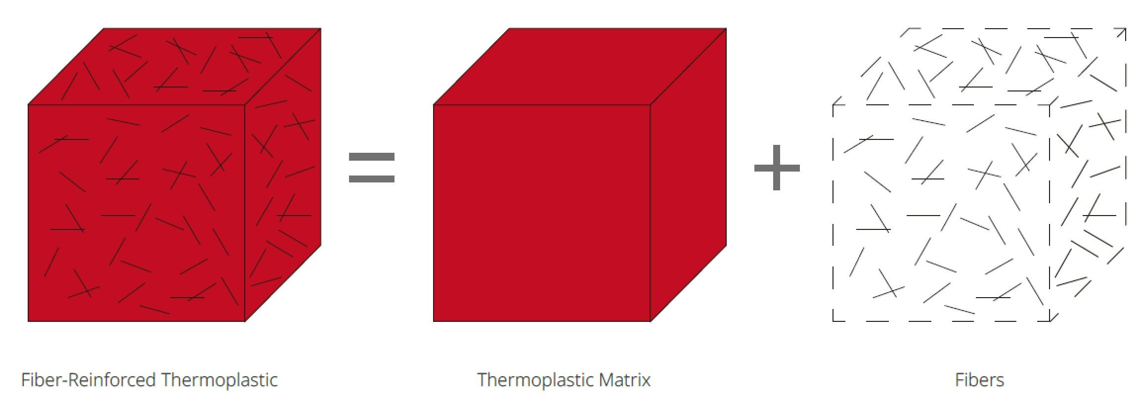
The 3D printing profile is a data pack composed of a complete list of print settings and parameters. It not only covers the basic settings related to 3D printing, such as layer, platform addition, speed, and support, but also contains more advanced settings such as filaments, printers, and extrusion control. The profile is used to control your printing procedure when converting models into G-Codes that the 3D printers can understand.

The usual format of the profile is the .bin format. ideaMaker has built-in profiles of different qualities for a variety of filaments. For example, ideaMaker provides “High quality”, “Standard”, and “Speed” profiles for Raise3D E2 printer. These profile files have been repeatedly calibrated by test engineers to be effective. However, whether it’s someone new to 3D printing or a senior test engineer, optimizing parameters is a repetitive and troublesome process. In this process, users need to repeatedly modify those parameters and 3D print the G-Code file to verify it. This takes a lot of time and can be costly.

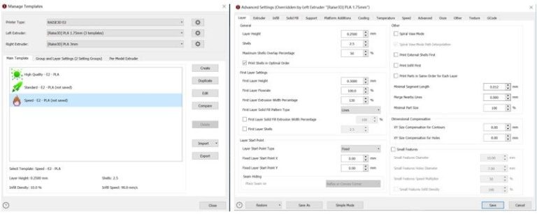
Figure 1 The slice template provided by ideaMaker.

What is Profile Iterator?

In order to simplify the calibration process and to improve the profile itself, Raise3D launched a systematic and visual test assistant – Profile Iterator.

Profile Iterator is really a multi-stage human-computer interaction system. The user will complete the interactive test with the Profile Iterator step-by-step, and then get the results. The figure below is its basic interaction logic.

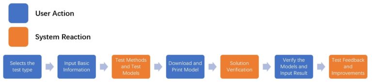
Figure 2 The Process of Multiple Human-computer Interactions between User and Profile Iterator.

Users only need to follow the prompts on the web page to complete the test process. Profile Iterator will provide users with potential causes of problems when printing. More importantly, Profile Iterator will help users to verify whether the current profile is the best one and calibrate it.

What types of tests does the Profile Iterator provide?

Profile Iterator currently provides two types of tests, with a total of 5 test options. Not every test needs to be completed, and you can choose a single test according to your needs. Of course, you will get a better profile if you complete all tests.

  1. Basic Calibration

Basic calibration includes Temperature Test and Flowrate Test. These two tests involve printing temperature and infill flow, which directly affect the overall integrity of the final model.

Profile Iterator aims to help you find the best printing temperature and flow rate for your filament. When you use a new printer or new filaments, it is recommended that you run Basic Calibration.

1)  Temperature Test

In the Temperature Test, Profile Iterator will provide a temperature tower model to test the print quality of the model at different temperatures and help users find the best temperature.

2)  Flowrate Test

Flowrate Test requires the printing a two-layer hollow cube using the profile the user wishes to verify and test the thickness of each side of the cube in order to measure the optimal flow rate percentage.

  1. Feature Tests

If you have completed the basic calibration, or want to improve the profile further, you can perform the Feature Tests. Profile Iterator provides four types of Feature Tests to address common problems with the model.

1)  Vertical Surface Test

Users need to print the cube to calibrate the temperature and flow settings.

2)  Ghosting Tests

Users need to print a custom 20x20mm cube to test for ghosting problems.

3)  Start/End Points

Users need to print the block model to check the start/end printing results.

4)  Top Surface Test

Users need to print the block model and analyze the printing effect of the top part.

How to use Profile Iterator

Step 1. Upload

Click “Upload” to upload the .bin file and enter the Profile Iterator test page.

Step 2. Select Test

To start a test, click “Start” under a test icon (Here takes “Temperature Test” as an example).

Step 3. Input Basic Information

Enter the printer information and what kind of filament you use, then click “Next”. You need to enter accurate printer and filament information.

Step 4. Test Model and Test Methods

Profile Iterator will provide the specific test methods. You need to print a temperature tower model which has 5 parts, ranging from A to E. Each part is printed at a different temperature in the same interval (for example, the printing temperature of part A is 195°C, and the temperature of part B to E is increased by 5°C). Profile Iterator will automatically generate the temperature interval and fill in other parameters (such as infill density, build plate temperature, etc.), and you can also manually set the temperature range. After the setting is complete, click “Next”.

Step 5. Download and Print

Profile Iterator will generate a test G-Code file based on the data you filled in the previous step. You need to download the file and print the model on your 3D printer.

Step 6. Validate Test Result

When your model is successfully printed, return to the Profile Iterator and click “Validate Test Result” to start verifying your model. Profile Iterator provides a specific verification scheme. For example, the Profile Iterator here requires you to check the overall condition of the printer and the model. If the printer is noisy when printing, or the model skips layers or has tiny air bubbles, there may be problems with your printer and its filaments. You can find a specific solution by following the prompts in the picture.

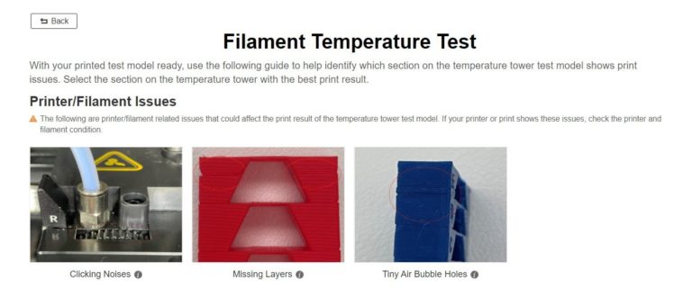
Figure 3 Issues you may meet when printing, such as clicking noises, missing layers, air bubble holes.

Next, we will further verify how temperature influences the final model. Profile Iterator provides four types of indications of problems caused by using improper temperature, such as stringing, drooping bridges and overhangs, etc. Check which part (A to E) of the temperature tower model has the best print quality, and which part has the problem.

Just like when answering multiple-choice mathematical questions, you only need to answer the questions provided by Profile Iterator based on what you see. For example, the Profile Iterator here asks you to “Please select the section on the test model with the best result.” You can choose the correct answer according to what you observe on the printed model.

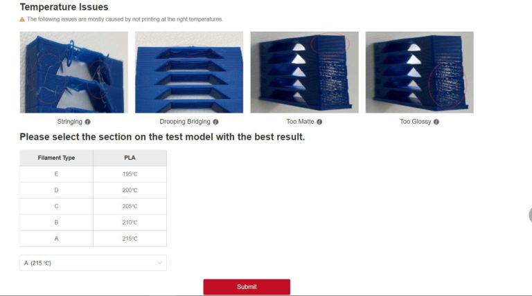
Figure 4 Issues with temperature, such as stringing, drooping bridging, too matte and too glossy.

Step 7. Acquire Validate Result

At this point, you are about to get your final answer. If you think that the printing temperature of Part A is 215°C is the best printing temperature, select the answer and submit the test. Profile Iterator will confirm that 215℃ is the best printing temperature for your profile and update it. You can download the updated profile and use it directly in the slicing software!

If the test result you enter is far from the standard result of Profile Iterator, Profile Iterator will ask you to reset the profile parameters and test again (below is the Flowrate Test as an example).

On completing the test, you have obtained an iterative profile file. You can perform other tests or start a new print.

Application of Profile Iterator

Profile Iterator provides users with an automatic profile file that allows them to verify their printing profiles on their own. With Profile Iterator, whether you are a 3D printing novice or a test engineer, you can quickly find the cause of problems with the print model, and better optimize the profile file.

Profile Iterator can also be linked with the slicing software, ideaMaker, and the powerful database ideaMaker Library, in order to obtain online high-quality profiles of various models shared by users around the world. Users can download these files and use Profile Iterator to ensure the profile files that meet their needs. ideaMaker Library has also launched a profile generator and comparison software. Users can generate profile files online or compare them.

In the future, Profile Iterator can be used in calibration, iteration, and mass production processes to further enhance industrial production and individual users. It will help them use new printers and filaments, as well as aid them to complete batch profile verification.

6 Common Brass Insert Designs in 3D Printing

3D printed parts are generally not used alone, they are generally mounted to an assembly. One of the methods used to mount the part is through inserts. There are many insert designs, each with their own strengths and uses. The right insert design for you will partly depend on your application. Recently Raise3D tested 6 commonly used brass insert designs in 3D printing using two different 3D printing materials, Nylon X and PLA.

What is a Brass Insert? What are Inserts Used For?

In most 3D printing applications, a 3D printed part is not used alone. It is commonly used as part of an assembly, where it will be mounted to other parts within a system. Using a threaded brass insert can simplify the process of modeling parts, and help better guarantee thread consistency across multiple prints. Brass inserts also are better suited for repeated use and are less likely to degrade over time.

What is a Pressed Insert and a Heat Set Insert?

The difference between pressed inserts and heat set inserts is that one uses pressure to install the inserts while the other relies on heat.

A pressed insert is when an insert is aligned into a predetermined hole, and inserted using pressure and force. One example of how this can be done is by drilling a hole and using a hammer to lightly tap the insert into the hole.

A heat set insert is when an insert is aligned with a predetermined hole, and heat is applied to the insert. This causes the insert to heat up, melting the surrounding material. When pressure is gently applied, the insert will go down to the desired depth. One way to heat the insert is by placing a soldering iron to the insert.

What Are Different Designs for Inserts in 3D Printed Parts?

We tested six common designs for installing inserts in a 3D printed part.

1. Horizontally Oriented Printed Parts using Brass Insert:

These parts are produced with the model-oriented so that the layer lines are perpendicular to the direction of the insert hole path through the part.


2. Vertically Oriented Printed Parts using Brass Insert:

This style uses the exact same design and model as the previous method, however, the part is oriented so that the layer lines are parallel with the path of the hole through the part.


3. Reverse Insert:

This design features an insert that is installed through the part to end up recessed under the outer surface. A gap, similar to an insert hole, runs through the entire part and the insert is driven through the part where the bolt will be used on the other side. This method is better suited for shallow parts.


4. Embedded Nut:

This design features a nut that is dropped into the part in the middle of the 3D printing process.


5. Slotted Nut:

This design features a slot in the back that the nut is dropped into.


6. Printed Thread:

The thread is modeled into the part’s geometry and printed as part of the piece itself.

Each of these designs has its own uses and benefits. Depending on the application, one design may be better suited than another.

Testing 6 Different Insert Designs

To test the six different insert designs described above, Raise3D designed a carbon fiber nylon printed base at 90% infill which remained mounted to a frame. Then insertable core designs which only took 45 minutes to print, were inserted into the carbon fiber nylon base. The cores were designed in accordance with the 6 different insert designs in two different 3D printing materials, PLA and Nylon X.

1. Horizontally Oriented Printed Parts Using A Brass Insert

For this design, the cores were printed and the inserts pressed in from above.

The PLA printed cores tend to break away at the back area in the direction of the force. However, the Nylon X cores almost slip out rather than breaking like the PLA printed cores.


Horizontal Hole Pressed Insert

Horizontally Oriented Printed Parts Using A Brass Insert

2. Vertically Oriented Printed Parts using Brass Insert

The cores so that the layer lines are parallel with the path of the hole through the part. The inserts were pressed in at the top.

The PLA printed core behaved more like the Nylon cores, in that the inserts slipped out. The Nylon X printed cores broke in the same way as the Horizontal printed holes.


Vertical Hole Pressed Insert

Vertically Oriented Printed Parts using Brass Insert

3. Reverse Inserts

In this design, inserts were placed backward through the parts. The nut catches on a lip, which embeds the nut further into the 3D printed parts.

The PLA printed core almost separated from the main block while the core insert almost stayed in the block entirely. However, it reached 100 pounds before breaking. The deeper the inserts are set in, the stronger the inserts will be. The Nylon cores reached up to 80 pounds before failing.


Reverse Insert

Reverse Insert


Reverse Insert Front

Front of the Reverse Insert

4. Embedded Nut

In this design, nuts were used as the inserts. During the printing process of the 3D printed cores, the printer is told to pause at a certain height directed in the Gcode. Only one pause was used to create these inserts, but this process can be repeated multiple times in a single print.

This means the cores will print up to a certain height and pause. When the printing is paused, a nut is dropped into the part, before printing continues, sealing the nut inside the cores.

For both PLA and Nylon cores, the tops of the cores tended to break off the upper layers of the core insert around the pause height instructions. However, the PLA printed cores reached up to 62 pounds of force before breaking off the top while Nylon X reached 58 pounds of force.

Embedded Nut

Embedded Nut

5. Slotted Nut

In this design, nuts were used as the inserts again. However, rather than dropping the nut in and continuing to print, the nut is slid into the 3D printed part afterwards.

Both PLA and Nylon cores broke in a similar fashion as the cores from the Embedded Nut design. However, PLA reached to 67 pounds of force before breaking, while Nylon X reached 80 pounds before breaking.

Slotted Nut

Slotted Nut

6. Printed Thread

This design does not use any inserts or nuts. The thread pattern is already printed into the part.

PLA printed cores took about 67 pounds before they broke. The Nylon X cores reached 112 pounds before they broke.

Printed Thread

Printed Thread

Related Brass Inserts Videos

Connect with Raise3D:

Have you had a great experience with Raise3D that you would like to share? Please contact us at inquiry@raise3d.com. We look forward to hearing from you.

For more information about Raise3D printers and services, browse our website, or schedule a demo with one of our 3D printing experts.


How to Apply Embedded Texture in ideaMaker

IdeaMaker Texture features an Embedded Texture option that supports the pairing of an image with model files. This feature is useful for 3D scanning projects where object geometry and surface color are captured and mapped together. An example of the file format for this type of model is .OBJ.

Applying an embedded texture is a simple procedure. First import the .OBJ file (ideaMaker 4.1.0 only support .OBJ,more image-embedded format will be supported in later version such as 3mf), then click “Texture” on the tool bar, thrn choose Embedded Texture from the pop-up menu. Since the image is already mapped within the .OBJ file, there is no need to adjust it. Once the embedded image is applied, ideaMaker will automatically generate a 3D texture according to the greyscale value contained within the colors of the image.


The user needs to provide accurate data for Embedded Texture. The data should include the .OBJ, image file (.JPG, for instance), and mapping information (.MTL, for example). ideaMaker currently only supports one image per model file at a time as an embedded texture. The documents of this example shown above in this article can be downloaded here.

How to Apply ideaMaker Library Textures in ideaMaker

Texture in ideaMaker offers the ability to apply texture patterns to 3D-printed objects and the possibility to share textures with other 3D printer users. It is a straight-forward feature that both those with a more advanced design skill level and those who are starting to learn to design can efficiently use.


Wide-ranging Textures, Far-reaching Possibilities a Download away

ideaMaker Library Textures provides users with a large diversity of texture patterns, where users can not only download the texture patterns officially provided by ideaMaker for free but also get hundreds of texture patterns uploaded by other users.

Users can import textures from ideaMaker Library Textures to ideaMaker with one click, a very quick and easy process and allows users to load textures for the model in one step.

ideaMaker Library Textures also provides a texture-sharing platform for 3D printing enthusiasts. Users can share the textures and patterns they create to ideaMaker Library Textures, as well as the parameters and techniques for using them.


Quick One-Click Import

When adding textures to the model, select “Import from ideaMaker Library” to import textures from ideaMaker Library Textures with one click.

1. Select “More”, and then select “Import from ideaMaker Library”, to automatically be directed to the ideaMaker Library Textures page.


2. To search for the desired texture, type keywords such as the name, color, or author of the texture pattern into the search box. The texture page contains the name, an introduction, the author and description of the texture, as well as the parameter settings the author recommends for using it.


3. Click “Import to ideaMaker” on the texture page to import the template into ideaMaker with one click.


An Easy to Apply and Adapt the Texture

1. Keep your ideaMaker open and import the model.


2. Find the desired texture pattern in ideaMaker Library Textures and click the “Import to ideaMaker” button on that page.


3. Copy the link in the pop-up box, and then return to ideaMaker.


4. ideaMaker will remind you to download the texture. Follow the prompt.


5. You have successfully loaded the texture onto the model! You can adjust the parameters according to your needs to get the appearance you require.


One-Click Export, Share Your Ideas

If you have created a texture pattern you like, you can share the texture to ideaMaker Library Texture with one click in ideaMaker. You can also share the parameters on how to apply this texture pattern with other 3D printing enthusiasts.

1. Select the “+” in the Texture toolbar to import the local texture pattern you have drawn.


2. Select “More”, then select “Export to ideaMaker Library”.


3. ideaMaker will automatically redirect to the uploading interface in ideaMaker Library Texture, where you can edit the texture name, image, setting parameters and other information. Make sure to log into your ideaMaker Library account first.


You have now learned how to import textures form ideaMaker Library Textures, and how to upload your textures to share with other users.


It is time to get creative with the way you make models look and share your work with other 3D printing enthusiasts!


If you have any questions about the ideaMaker Library Textures, or want to inquire about ideaMaker related information, please feel free to contact inquiry@raise3d.com.