With ideaMaker Texture, the user can skip lengthy CAD processing and generate a 3D texture directly from a 2D greyscale image, and can apply it to the model’s surface. Examples of 2D images that can be spread over a model’s surface include patterns, figures, or logos. ideaMaker uses slicing to automatically convert any image into a 3D texture to be printed as a unique surface finish. ideaMaker Texture expands the possibilities of a model’s appearance while broadening the appeal of it.
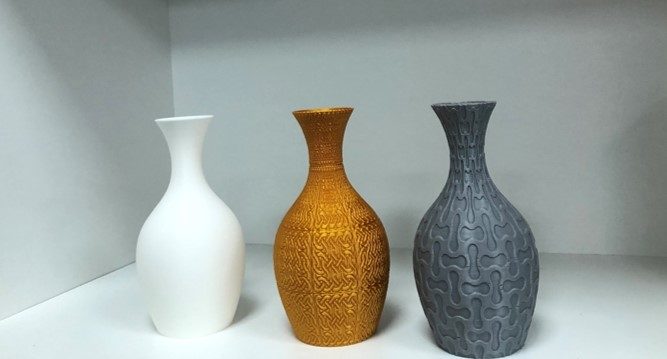
Vase with Texture applied
What can Texture be applied for?
Texture can easily turn any 2D image into 3D texture on a model’s surface. This enables the user to try out an unlimited amount of images for a huge range of appearances. This is useful for any scenario that requires customization, with customized digital product appearances benefitting especially. Examples of customized digital product appearances include headphones, controllers, automotive interior parts, artistic crafts, household products, miniature architecture, and computer mice.
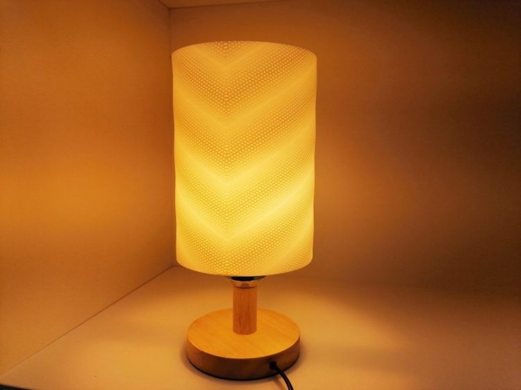
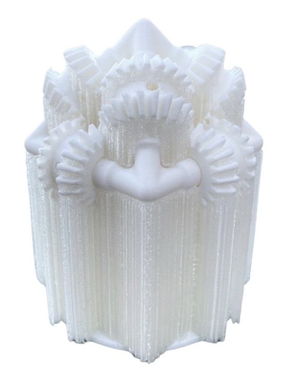
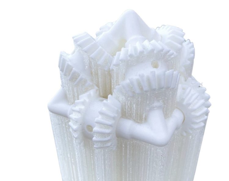
Lampshade with Texture
A great example is to apply Texture on Print+, a DIY headphone kit that uses 3D-printed casing. It is designed to be printed with Polymaker’s PolyMax PLA, which provides a wide range of color options. Now, with ideaMaker Texture, the user can customize the 3D texture of a headphone case even further, using any greyscale image they like.
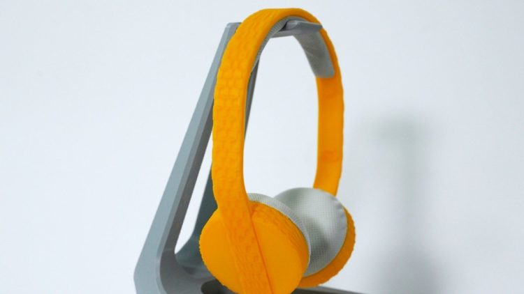
DIY headphones with texture
Benefit of Texture
ideaMaker Texture is user-friendly and saves a significant amount of time when compared to conventional modeling requirements and procedures. Textures can be modified by applying a 2D image and changing a few settings. This easy-to-use feature gives those still learning modeling skills the possibility of customizing the surface of a 3D printable object with a texture. There is a Texture module in ideaMaker Library which provides a vast number of 2D texture images, and where the user can import a texture image from an online library to ideaMaker with one click, as well as also having the option of uploading a local image they designed to ideaMaker Library, and share the texture, the model appearance design, and customization experience.
Texture is easy to use and only takes a few steps to generate the 3D texture on a model. All that is necessary is to import an .STL into ideaMaker 4.1.0, then click the Texture icon in the toolbar and choose an image. Then adjust the texture mapping by degree, position, and number of duplicates until achieving the desired parameters. After that, the user can slice and preview the resulting application of the 3D texture on the surface of the model.
How to use Texture
The process of applying Texture is designed so that beginners and non-professional designers can fully utilize this feature, only needing 4 steps.
Step 1:Import Model
- Open ideaMaker 4.1.0 and import your model for slicing. If your ideaMaker version is lower than 4.1.0, please visit Raise3D Download Center and download the latest ideaMaker.
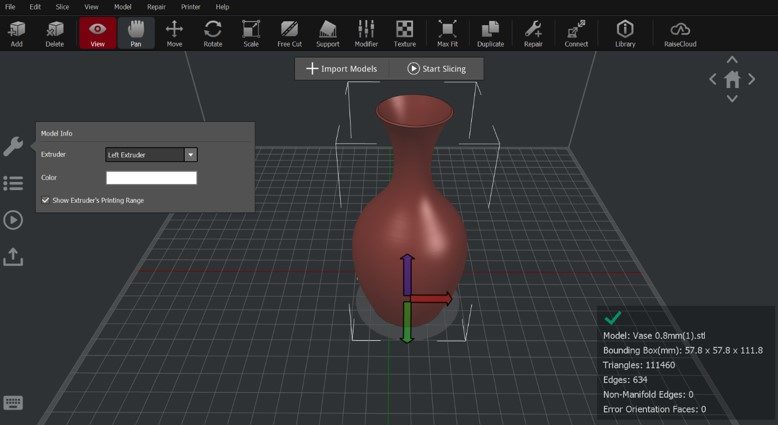
Import model
Step 2: Add and Adjust Texture for Model
- Select the model and click the Texture icon in the tool bar. Select “Custom Texture” from the pop-up menu to select customized texture image.

- Click “+” in the “Custom Texture” menu, then upload a texture image. ideaMaker will automatically generate a 3D texture according to the information in the image. ideaMaker provides the user certain parameters to adjust the wrapping of the image. Basic and advanced settings will be discussed in later chapters.

There is no image requirement for size, format, color or resolution (supported format includes .jpg, .jpeg, .bmp, .png, .texture). ideaMaker will convert information in the image to greyscale values. The greater the contrast in the picture, the more notable the 3D texture will be on the model.
Based on image content, the user can apply Texture to a variety of situations including pattern (left), figure (middle), text and logos (right).

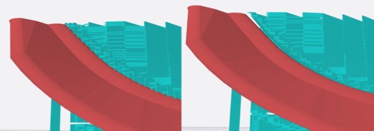
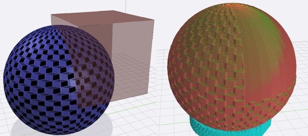
In ideaMaker 4.1.0, Texture cannot be applied on a flat surface of the model that is parallel to the print bed. Therefore, when adding a textured image, the user should consider the model’s orientation and the mapping of an image on the model’s surface.
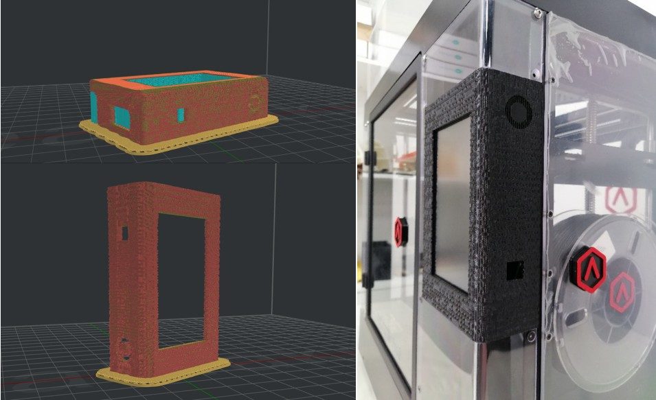
Different result of Texture for model in two orientations
Step 3: Preview of Texture Result
In the slicing preview, the user see what the 3D printed surface with texture looks like.

Step 4: Print! Make a Model with a Unique Appearance
Once the Gcode is uploaded to the Raise3D printer, it will take care of the rest. The user will finally possess a creative and unique model. Post-processing, such as painting, polishing or UV printing, can give extra appeal to final object.
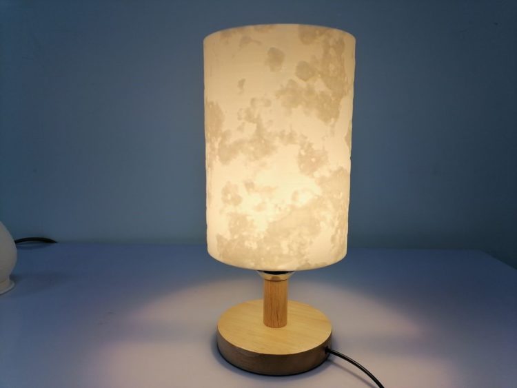
Lampshade with Moon surface applied using ideaMaker Texture
Basic Tuning for Texture
ideaMaker 4.1.0 provides several useful settings to easily customize the application of a texture.
1. How to shift texture on the model?
Changing values in “Move” will shift the texture on the model. Please note, texture in ideaMaker 4.1.0 is wrapped according to axial symmetry. A value in the first box will decide the horizontal offset between the texture and the axis.
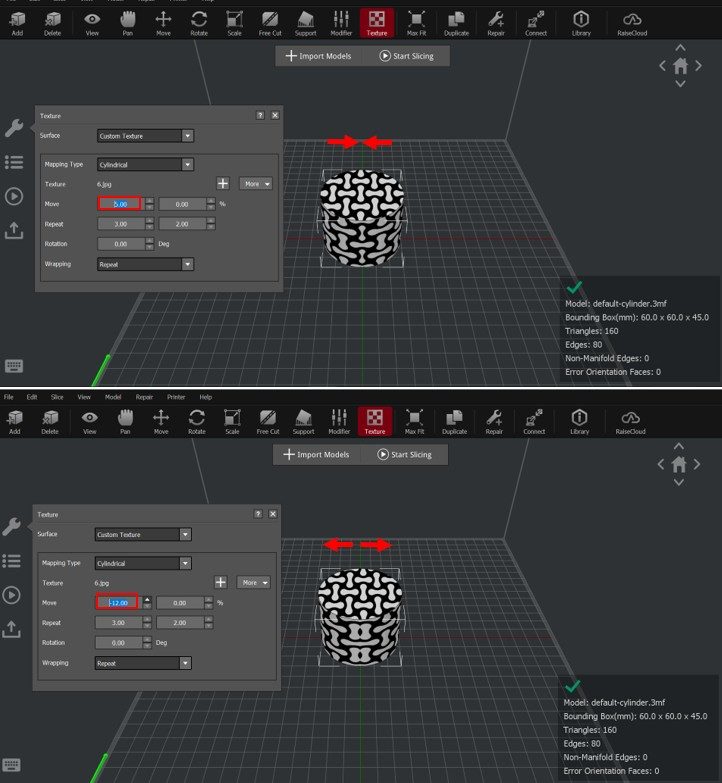
Positive value: Textures will move closer to the axis; Negative value: Textures will move away from the axis
A value in the second box will decide the offset in the vertical direction.
Positive value: Texture moves downwards; Negative value: Texture moves upwards
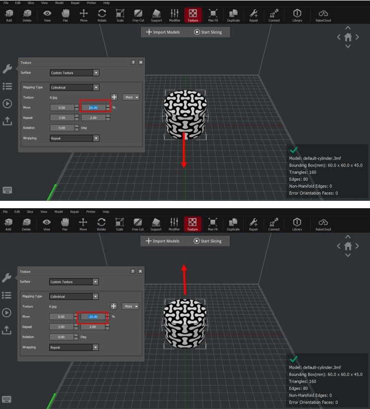
2. How to Adjust the Repetition of Texture
Adjusting the value of “Repeat” changes how the texture repeats. A value in the first box adjusts the way the pattern repeats in horizontal directions while a value in the second box decides repetitions in vertical directions.
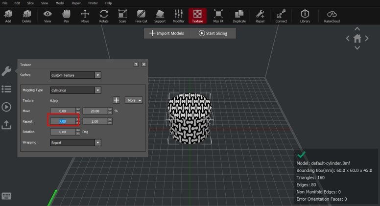
Adjusting horizontal repetitions
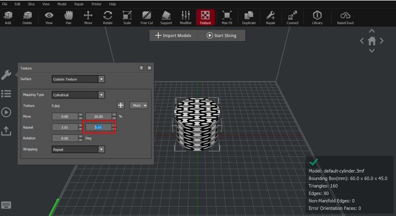
Adjusting vertical repetitions
3. How to Rotate the Texture?
With “Rotation”, the texture will rotate clockwise or counter-clockwise along the axis.
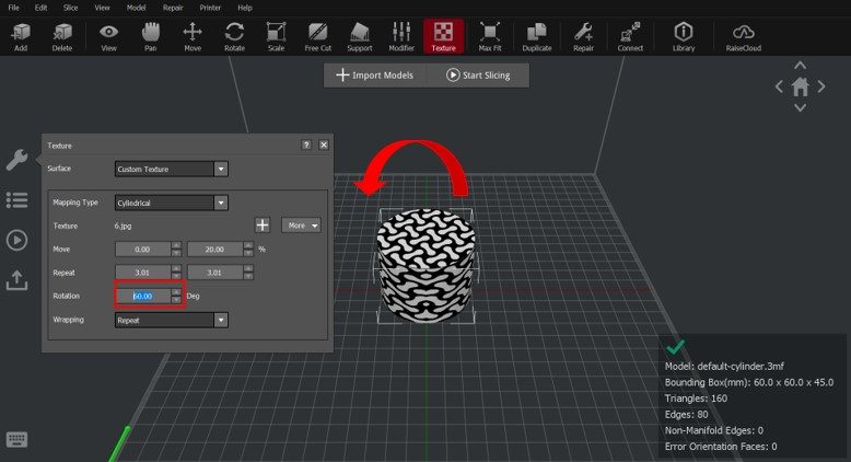
Positive value: Counter-clockwise rotation
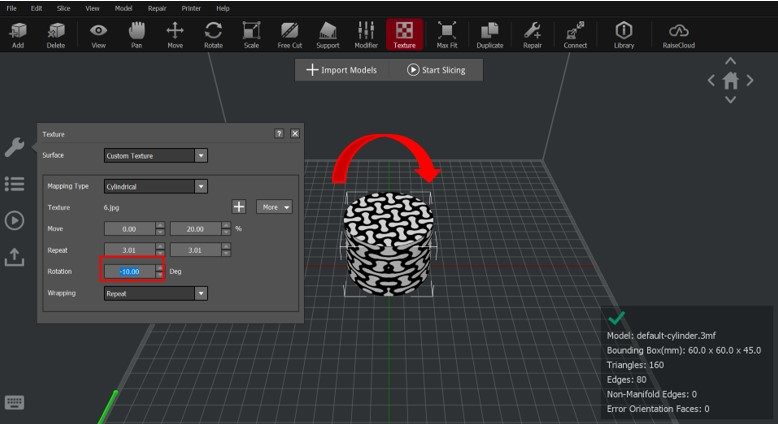
Negative Value: Clockwise rotation
Advanced Settings of Texture
Besides adjusting the arrangement of texture on the surface, a user can also change settings in the “Texture” category of slicing templates. Some useful options include Texture Resolution, Texture XY Offset and Texture Outside Only.

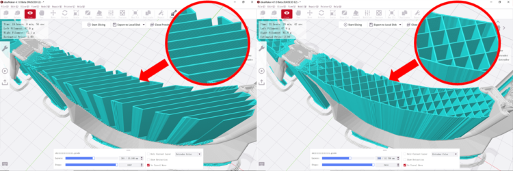
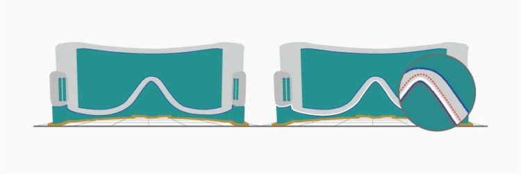
Texture Resolution decides how accurate the image will be when converted into 3D texture. The higher the value is, the sharper the 3D pattern will be.
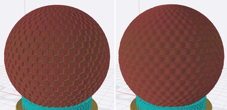
Left: Resolution=0.1mm; Right: Resolution=0.5mm
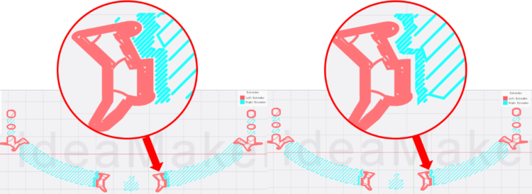
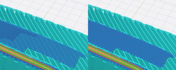
Texture XY Offset decides how much of the model surface will be extruded or pulled based on the texture image within a certain grey value. The larger the number is, the more pronounced the extrusion or pull will be. A negative value inverts the direction of the extrusion or pull.
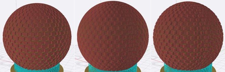
Left: Offset=1.00mm; Middle: Offset=0.5mm; Right: Offset=-1.00mm
A user can enable Texture Outside Only to allow ideaMaker to identify inside the surface of the model and add texture to only to the outside. For typical geometry, like a vase, ideaMaker can identify its inside and keep in its original, non-textured state.
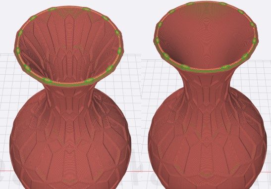
Left: Texture Outside Only=Disabled; Right: Texture Outside Only=Enabled
In addition, the user can add modifiers to block certain areas from generating texture.
Texture is not applied in an area blocked by a modifier
How to Acquire A More Textured Image?
Use ideaMaker Library to acquire high-quality textured images.
ideaMaker Library now has a Texture category for users to upload and download free images of textures, which supports one-click import and share.


Now that you understand of the functions of ideaMaker Texture, you can 3D print your own creations using Texture.
If you have any additional questions about the ideaMaker Library Textures, or want to inquire further regarding ideaMaker, reach out to us at inquiry@raise3d.com.