+1 888 963 9028

How to Connect a Third-Party 3D Printer to ideaMaker?

Before slicing the model in ideaMaker, you need to match your printer with ideaMaker, so that the slicing settings of the model will match the printer you are using. ideaMaker provides you with a variety of built-in printer types. If your printer is not in the list of ideaMaker supported printers, you need to manually configure the third-party printer in ideaMaker.

Part 1 General Settings

1. Make sure you have downloaded and installed ideaMaker.

Note: To upgrade or download ideaMaker, please visit the official website: https://www.raise3d.com/download/.

2. If you are configuring a third-party “printer” in ideaMaker for the first time, please select “Printer” in the menu bar, and then select “Configuration Wizard”.

Enter the Configuration Wizard

Figure 1 Enter the Configuration Wizard

3. There is a preset list of all printers supported by ideaMaker in Printer Type. If your printer model is in the list, select it directly. If you want to add a third-party printer, select “Other (Third-party Printer)”.

Select “Other (Third-party Printer)”

Figure 2 Select “Other (Third-party Printer)”

4. In the “Add Printer” interface, you can set the specifications and parameters of the third-party printer here.

A) Modify the printer name and abbreviation.You can enter the name of the printer in “Printer Type”. For example, set the third-party printer to “new printer” here.“Printer Type Abbreviation” refers to the abbreviation of the printer model (optional).

Set the nozzle and other parameters

Figure 4 Set the nozzle and other parameters.

B) Set the nozzle and build plate parameters according to your printer.

  • “Nozzle Diameter”: The diameter of the nozzle.
  • “Build Width”: The maximum printable width, which needs to be set according to your build plate specifications.
  • “Build Depth”: The maximum printable depth,which needs to be set according to your build plate specifications.
  • “Build Height”: The maximum printable height, which needs to be set according to the lowerable height of your printer’s Z-axis.
  • “Distance From Border of Build Plate” refers to keeping a safe distance from the border of the build plate.

Note: This function is to check if models are placed outside of the extruder’s printing range.


Set “Distance From Border of Build Plate” to 20 mm

Figure 5 Set “Distance From Border of Build Plate” to 20 mm

  • “Build Plate Shape” refers to the shape of build plate. There are two shapes: “Rectangle” and “Ellipse”.


Build Plate Shape

Figure 6 Set the shape of the build plate


  • “Bed original at the center” with this function enabled, the original of coordinates in the G-Code file will be set as the build platform’s center point. With this function disabled, it will be set as the build platform’s left-front corner.

Note: 1. This function works only for third-party printers.

  1. Make sure the printer firmware supports it before using this function.
  • “Firmware” refers to the motion controller board firmware type. You can choose “Marlin”, “Raise3D Pro2” and “RepRap Firmware”.
Select the motion controller board

Figure 7 Select the motion controller board

  • Set the relevant parameters of the extruder.

C) Set the relevant parameters of the extruder.

  • Set the number of extruders. If you are using a single extruder, select “1”; if you are using a dual extruder, select “2”

    Select the number of extruders

    Figure 8 Select the number of extruders

  • Select the filaments used for the main extruder. It is recommended that you use Raise3D official filaments.

    Select the Filament Used

    Figure 9 Select the filaments used

D) Set the Sequential Printing

Sequential Printing

Figure 10 Sequential Printing

  • Gantry Height” for Raise3D Pro2 series printer, refers to the distance between nozzle and crossing rods to avoid collision in sequential printing. For Raise3D E2 printers is a random number made up by our developers.
  • “Allow Custom Printing in Sequential Printing” refers that with this function enabled, you can arrange printing order of the models manually.
  • “Validate Printing Priority before Slicing” means that after enabling this function, ideaMaker will check whether the print order of the model is valid. Please refer to ideaMaker User Manual 4.5.4 Sequential Printing for more information.

5. Set the G-Code file export method. When slicing, you can export the slice file to a local disk, and you can also upload the slice file to a printer or upload to the RaiseCloud and the OctoPrint.

Set the G-Code file export method

Figure 11 Set the G-Code file export method

Here you can fill in the URL and API key to setup OctoPrint.

Configure the OctoPrint

Figure 12 Configure the OctoPrint.


Part 2 Advanced Settings

Advanced settings interface

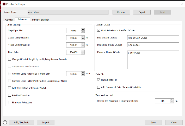
Figure 13 Advanced settings interface

1. After you complete the general settings of the printer, you can set the advanced settings of the printer.

D) Step-E per MM “Step-E per MM” refers to the steps required to extrude 1mm filament.


E)  X axis Y axis“X-axis compensation” refers to model size compensation in X axis. “Y-axis compensation” refers to model size compensation in Y axis.


  • For example, the model’s design size is 100mm, but the printed model’s measured size is 102mm, that means the X-axis compensation is 100mm/102mm*100%=98.04%.
  • The model’s design size is 100mm, but the printed model’s measured size is 98mm, that means the Y-axis compensation is 100mm/98mm*100%=102.04%.

Note: Dimensional deviation may be caused by filament flow rate, mechanical deviation (such as belt tension) and so on. This function only works for XY axis mechanical deviation.


  • “Change GCode E length by multiplying filament flow rate”, refers that with this function enabled, the global flow rate will not be controlled by code M221 anymore but always keeps at 100%. The E value in the G-Code file will be edited directly, so that the motion board doesn’t need to calculate flow rate.

F) Independent Dual Extrusion “Independent Dual Extrusion”, with this function enabled, ideaMaker will allow printing with Duplication and Mirror mode.

Note: The printer should have at least two print heads for this feature. For Raise3D printers, only E2 printers can enable this function.


G)  The Default Value is 150mm“Confirm Using Raft if Size is more than”, with this function enabled, ideaMaker will automatically measure the model’s width and depth and print with a raft if it is bigger than set value. “Confirm Using Raft if Printing Mode is Duplication or Mirror”, with this function enabled, ideaMaker will automatically printing raft when the Duplication or Mirror mode is selected.

Note: The default value is 150mm.


H) Wait for Heating at Extruder Switch“Wait for Heating at Extruder Switch” when this function is enabled, the system will wait for heating to the target temperature for switching extruders.


I)  Relative Extrusionwhen this function is enabled, the system will output relative E values instead of absolute values in the G-Code files.

Note: 1. This function works only for third-party printers.

2.Make sure the printer firmware supports the relative extrusion before using this function.


Firmware Retractionwith this function enabled, the retraction and restart commands of G1 will be replaced by G10/G11.

Note:

  1. This function works only for third-party printers.
  2. Make sure the printer firmware supports the firmware retraction before using this function.
  3. Set up Custom G-Code. ideaMaker will avoid outputting M1001, M1002 and M2000 for third-party printers, and instead of alternate GCode set as the following figure.

    Set up Custom G-Code

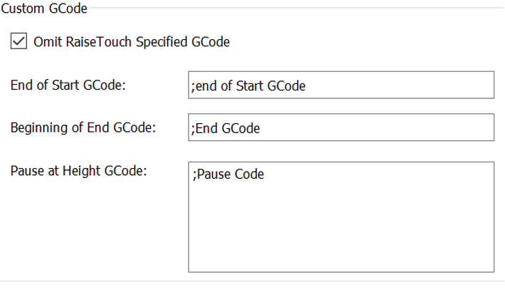
    Figure 14 Set up Custom G-Code

  4. Set up the Data File.

    Output Data Filewith this function enabled, ideaMaker will not export Data file, and it will lead to that the models preview images can’t be displayed in touchscreen.Figure 15 Set up the Data File.

    Add Content of Data File into GCode Filerefers that with this function enabled, the information of .data files will be add into the G-Code file, and the G-Code file can be import into ideaMaker as a template slicing file.

    Note: For third-party printer, it is recommended that this option can be turned off to improve compatibility.

  5. Set the maximum temperature limit setting of the heated bed.

    Temperature Limit

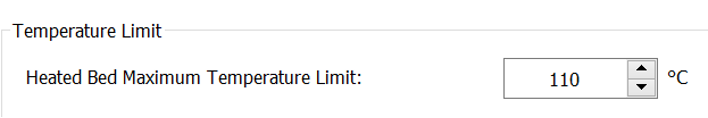
    Figure 16 Set the maximum temperature limit

Part 3 Extruder Settings

1. You can set the offset amount from the left side of the main extruder to the nozzle; the offset amount from the right side to the nozzle; the offset amount from the front side to the nozzle and the offset amount from the back side to the nozzle. For more information, please refer to 8.3 Extruder Settings.

Set the offset amount of the left extruder

Figure 17 Set the offset amount of the left extruder.


2. Set temperature limits for your extruder. It all depends on the temperature limit of the hot end you use.

Set temperature limits for your extruder

Figure 18 Set temperature limits for your extruder.


3. When you finishing the setting, click “Save”. Go back to the configuration wizard again, select your printer name “new printer”, confirm the number of extruders, the heated plate and the filament used. After all settings are complete, you can import your model for printing.

Finish the Configuration Wizard

Figure 19 Finish the Configuration Wizard.

Part 4 Configure the printer with two independent extruders

1. If your printer has the IDEX system (with two independent extruders), you need to configure the two extruders when configuring your third-party printer.

For example, select a third-party printer in the Configuration Wizard and name the new printer “new printer 1”. Select the number of extruders as 2, and set the filaments used for each extruder. Then set your left and right nozzle diameters and print bottom plate.

Configuration Wizard

Create a two nozzle printer

Figure 20 Create a two-nozzle printer.

2. Enter advanced settings, when your printer is equipped with independent dual extruders, check “Independent Dual Extrusion”, ideaMaker enables you to print in Duplication and Mirror mode.

Check “Independent Dual Extrusion”

Figure 21 Check “Independent Dual Extrusion”.


3. If you use Duplication and Mirror mode to print, check “Confirm Using Raft if Printing Mode is Duplication or Mirror”. When you print in Duplication or Mirror mode, there may be a slight offset between some nozzles. Therefore, enabling Raft will help to ensure that your nozzle doesn’t dig into the bed on one side. While the other one is printing perfectly fine.

4. Check “Wait for Heating at Extruder Switch” to ensure that when one extruder is switched to another, the hot end has fully heated up. Other settings are as set in Part 2.


Check “Wait for Heating at Extruder Switch”

Figure 22 Check “Wait for Heating at Extruder Switch”.


5. Enter the Left Extruder setting, set the offset value and maximum limit temperature of the left nozzle.


Set the offset value of the left nozzle

Figure 23 Set the offset value of the left nozzle.


6. Enter the Right Extruder setting, you can set the offset value X and offset value Y. If the offset value X and the offset value Y are both 0mm, you will get a virtual extruder offset. For more information, please refer to ideaMaker User Manual 8.3 Extruder Settings.

Set the right nozzle offset value

Figure 24 Set the right nozzle offset value.


7. When you have completed the settings, you can finish the configuration wizard and start to print.